EDIT…. the following mod is required for State of Charge (SOC) based operation of the Automatic Generator Start (AGS) discussed HERE.
Disclaimer: Although generally the same, there are differences between the various models and model years. The concepts discussed here are valid across the board. The details may vary. Also, there is some explanation of concepts that many of you already know, but I’m trying to help those who don’t know so bear with me! And, if I’m wrong on something please let me know so I can correct.
Some of the most frequent questions on social media involve the house bank and it’s capacity. “How long will my fridge run on inverter?” “How large a solar panel do I need?” “Do I have enough bank to boon dock for two days, a week?” and so on and so forth. Invariably the (correct) answer starts with “That depends……” It depends on how much energy you use and it depends on how big the battery bank is and it depends on how much electricity you generate. It requires identifying and budgeting your electrical needs and the amount of electricity you can produce and then monitoring both. The latter part, the monitoring, is what this mod is all about. You can control what you can measure.
First off, there are TWO battery banks. The chassis bank, which consists of two 12V batteries which are dedicated to running the vehicle needs like starting, engine/transmission control, driving lights, dash AC etc. Then there is the house bank which consists of four 6V batteries wired to provide 12V, as described below, and runs the inverter, house lighting, furnace, the DC control part of our roof AC’s etc. When the engine runs and the chassis batteries are sufficiently charged an isolation relay closes and the house bank is also charged. When the engine shuts down the relay opens and you use strictly the house bank for house needs. This is so you don’t run the chassis bank down and end up unable to start the engine. There is an emergency switch on the center console which can force the relay closed to get electricity from the house bank to the engine starter in case the chassis bank is insufficiently charged. Finally, when you plug in shore power or run the generator the inverter/charger charges the house bank, until it is full, and then it charges the chassis bank. This is what happens when you see the glow/flashing in the “Emergency” button on the console.
What we are after here is knowing the SOC, state of charge, of the house battery bank.
Now, we all have those cute little red lights on our panels which tell you very little other than “close to full” or “not full”. We can also look at our voltage on the Magnum remote, and from there estimate SOC. There are charts that equate voltage to SOC (on the internet, of course). Problem with this method is that current flow out of the bank affects the voltage. So, unless you turn everything off and let the bank rest for a while and THEN read the voltage this too is not useful information.
See, there is only ONE method to accurately monitor SOC and that is to count Amps. Voltage is potential, amps is the FLOW of electricity out or in, subject to demand/production. Multiply the two and you have Watts, total energy usage. Volts x Amps = Watts Example: A 60W lightbulb operating on 12V will draw 5A. Count the amps over time and you know how much energy was drawn from the bank.
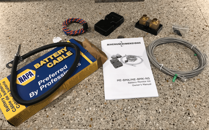
How do we count amps? This is where the BMK (Battery Monitoring Kit) comes in. It’s a Condition Monitor (same thing, different name) designed to plug right into the Magnum inverter charger with it’s readouts on the remote control panel upstairs. Plug and play! (Well, almost, some assembly required.) It’s available in a variety of places, including Amazon.

In addition you will need one ground cable. I got a 2’ 1/0 gauge battery cable from NAPA which should be enough to carry it all when wired. The amperage/wire gauge chart below shows that at 10-13 feet 1/0 gauge is good for 250-300A. My cable is only 2 feet so it should be able to carry even more, but the day to day loads should be well below that. The ONLY time there may be a larger load on the system is when the house bank is used to help start the motor via the emergency switch, and that circuit is fused to 300A.

Lastly you need a shunt. (The brass shiny thingy.) Some kits come with one, some don’t. They come in amperage ratings. Since the house users are fused at max 400A, and the inverter gets added to that I got a 500A shunt. Mind you, no one pulls 500A and at that rate the batteries wouldn’t last longer than minutes, not hours.
So, “HOW do it know”? The key piece in a condition monitor is that shunt. You install it in-line in the negative cable at the house bank. Attach the negative “load” (user) side to one terminal and the negative battery side to the other using the big bolts on the top. Because of the way it’s designed there is a TINY resistance between the two smaller connectors on the side, a resistance which is proportional to the flowing current. (Amps). This is where we attach a sensing wire, the blue/orange “twisted pair” which feeds into a little brain (the black box thingy) which calculates the flow. (Amps in or out). From there the data go via an RJ11 (phone) type cable to the inverter charger and then on to the remote display.
But before we install the shunt we need to understand how the house battery bank is put together and wired. In the Dragonship there are four 6V batteries that make up the house bank. One positive from one battery is connected to the negative of another (See red arrows in diagram below). This is called “in series”. ADD the voltages and the result is ONE 12V (two times 6) battery between the remaining minus and positive terminals. (One green box) Think of it as a 12V battery cut in half, with the two 6V halves connected with a cable (red arrows). Do this twice with a total of four 6V batteries and you essentially end up with two large 12V batteries. (Two green boxes) Then the two “12V batteries” thus created are wired “in parallel”, which means that the two Positives are combined, and the two Negatives are combined. (Yellow Arrows) When you do this the Voltage remains the same, but you double up on the capacity. (Amp hours, more on that later).

BTW, this schematic, minus my colored additions, is on the inside of the House Bank Compartment Door……VERY HANDY, thank you Forest River.
Note the three blue arrows. These are the negative connections to the house bank. One is the inverter, the other goes to the forward electrical compartment. The third goes to the chassis. The use of this term may lead to confusion so I will expound. “The Chassis” is the large, steel frame rail that is the back bone of our motorhome. The engine, axles and the house are mounted on it. It also serves as a huge electrical bus (connection point) for the negative side of the 12V electrical systems. Yes BOTH the House AND the Chassis Bank use the Chassis (steel frame) as the negative path for the electricity to flow. Electrons will flow back to whichever bank needs them to make up for the electrons lost. A joint supply path but NOT a joint return path…..confusing maybe, but the point is that the negative connection from the house bank to the chassis has nothing to do with the chassis bank. Two separate banks in spite of the joint supply path. (Electrons flow from negative to positive in a DC circuit….. this may seem counter intuitive…..) In addition there are also wired grounds directly to the battery, bypassing the chassis. Lights in a styrofoam ceiling have a ground wire, there is no metal work to tie in to. All the grounds are connected and a fat wire runs directly to the battery.
So, now that we know how the House Bank is put together we can install the BMK.
It is critical for the system to work that ALL electricity flows through the shunt to be “counted” and that no electricity gets in or out otherwise. So, I disconnected ALL cables from the minus side of the bank (Blue Arrows) and connected them to one side of the shunt. On the other side of the shunt I connected the 2’ 1/0 gauge, the one from NAPA, and connected it to the negative side of the bank. The bolt size on the shunt terminals is slightly larger than the battery posts. You will have to enlarge the holes in the existing cables. I used a hand reamer. It’s all copper and soft and enlarges easily.
From there it’s a matter of connecting the blue/orange sensing wire (pay attention, polarity i.e. which color where, matters), mounting the brain, and connecting the RJ11 cable to the Inverter Charger. Finally there needs to be power to the brain, which needs to come directly from the bank. So, an in line fuse on the positive side is required.


There, all done. Now we can run upstairs and see the wonder in action. Push the round knob on your remote panel, click to meter option three for the BMK and you will see how many Ah are flowing IN (charging) if hooked up to shore power or running the generator or engine, or OUT (discharging) if not charging. It will also count how many Amps have flown out since you charged the bank to 100%. There’s a bunch of other metrics too, read the instructions.
And now it gets interesting. Meter option 2 is SOC. After the bank is fully charged for a while and “thinking” this will be set to 100%. As you discharge it shows the percentage charge left in the bank. But percentage of what? Of your bank capacity, but to calculate it the BMK needs to know what that capacity is. The internet is overflowing with heated discussions on how batteries are rated and what it all means. It never stops. On the Dragonship the 6V batteries are labeled 220Ah reserve, 20 hours. What this means is that if you put a small to moderate load on the battery, in this case about 11A, it will last 20 hours, thus 220Ah. Larger loads deplete batteries faster AND less efficiently, and you get less Ah. Smaller loads will get more out. Add to that the age of the batteries and their temperature which also affect capacity. So, there are a lot of variables here, and it is certainly not an exact science at this level. Still a whole lot better than the little red lights.
IN THEORY two 6V 225Ah batteries in series create one 12V 225Ah battery. Two of these combinations in parallel, as installed here, create one 12V 450Ah bank. Real world results are usually less.
Again, this is a critical piece of information you have to give the BMK. In my case the number pre-programmed (By Magnum or Forest River don’t know) was 400Ah. Not a bad place to start and it leaves some fudge factor.


So now that we can MEASURE we can control. Disconnect shore power and watch the gauge. Turn on lights, the inverter, TV’s, plug in phones, run the furnace, the fridge. Right in front of you is the “speedometer” of your house bank. Lookie there, we’re pulling 40A….. Awesome, we’re good for 10 hours!
Not so fast pilgrim. You run your bank down to zero it’s not going to live that long, an expensive mistake. Not to mention the fact that the voltage would drop well below the minimum required by, for instance, the inverter and things would start shutting down. (For reference, the voltage of a 50% discharged lead acid battery is about 12.1V) Rule of thumb is that you run down to 50% and no more. Then it’s charging time. Now if you monitor the charging process you’ll find out that you can get back to 80% fairly quickly. That’s the “Bulk Charging” you see on the remote. The last 20% take a lot longer. So, realistically, 50% of a conservative 400Ah is 200Ah. If the fridge together with the parasite draw of the inverter pulls say 30A you’re good for a little over 6.5 hours, running non stop. Depending on the temperature in the coach it may cycle 50% of the time, which would make you good for 13 hours. Of course this is assuming there’s nothing else on.
So, here you have it. Measure/Monitor your load/charging and now you can observe/estimate/calculate how long your bank will last (without killing it) and how long it will take to recharge it, and thus when it’s time to fire up the generator/engine or plug in shore power. Not enough? Well, then you get the second most read advice on the subject: Larger Bank. And, it also answers the solar question: How big a panel? Enough to feed the need.
